3 Commonly Used EMC Components - Protection Devices
Introduction
In electronic products, the circuits that need to be protected are mainly power supply and signal, and the protection levels and protection schemes are different depending on the location. The three most commonly used protection devices are introduced: TVS tube, gas discharge tube, and semiconductor discharge tube.

Figure1: 3 EMC Components
Catalog
ⅠTransient Suppression Diode (TVS)
1.1 Device characteristics:
1.2 Volt-ampere characteristics:
1.3 Typical application:
1.4 How to Choose a TVS Diode?
Ⅱ Semiconductor Discharge Tube (TSS)
2.1 Device Characteristics
2.2 Working mode
2.3 Typical applications
Ⅲ Gas discharge tube (GDT)
3.1 Device characteristics:
3.2 Working process:
3.3 Typical Application:
3.4 How to Choose Gas Discharge Tubes?
Ⅳ TVS vs TSS vs GDT
4.1 Application fields:
4.2 Voltage class division:
Ⅴ Frequently Questions Asked about EMC Components
ⅠTransient Suppression Diode (TVS)
1.1 Device characteristics:
TVs, also known as transient suppression diodes, is a special diode made of semiconductor silicon material, and TVS is used in parallel with the protected circuit. When the circuit is normal, the TVS is in the off state, showing high impedance characteristics. When there is a surge voltage outside, it can change from high impedance to low impedance at a speed of nS in order to absorb the surge power, so that the surge voltage passes through itself to the ground. Thereby protecting the circuit from infringement. Its important characteristics are rapid response and short action time.
1.2 Volt-ampere characteristics:
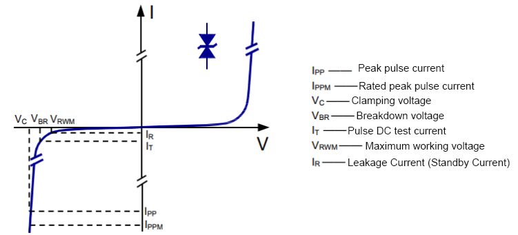
Figure2: Volt-ampere characteristics curve
As shown in the volt-ampere characteristic curve in the above figure, Vc is the clamping voltage and Vrwm is the highest working voltage, both of which are very important parameters in TVS selection. In order to be able to protect the protected circuit during design and selection, and at the same time not affect the normal operation of the subsequent circuit, Vrwm≥ the normal operating voltage of the circuit. In this way, when the circuit works normally, the TVS tube is in the cut-off state and does not affect the circuit; Vc≤ the highest voltage that the circuit can withstand, otherwise the clamping voltage maintained by the diode after encountering transient high voltage conduction will be higher than the withstand voltage of the subsequent stage circuit. Cause damage to the subsequent circuit. The followings are the specifications and parameters of the DIODES SMBJ5.0 series found on the component e-commerce platform. You can see that Vc and Vrwm of different models are different, and you can choose according to your needs.
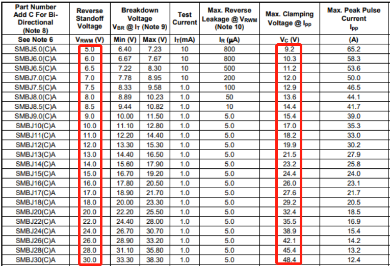
Figure3:Vc and Vrwm of different models are different
1.3 Typical application:
TVS tubes are often used in 485 circuits, 232 interfaces, USB interfaces, VGA interfaces, etc. that require anti-static and hot-swappable ports.
The following is a typical protection circuit of a USB 2.0 interface, which mainly protects the power line and differential signal DM/DP. When the transient high voltage coming from the USB interface, such as electrostatic coupling up to several thousand volts, is coupled to the signal line or power line, it will trigger the conduction of TVS D1 or D2 or D3 on the corresponding line, and release the instantaneous high voltage to PGND, thus realizing the protection of the subsequent chip and preventing the voltage of several thousand volts from passing through the signal line or power supply to the subsequent chip To burn out the chip.
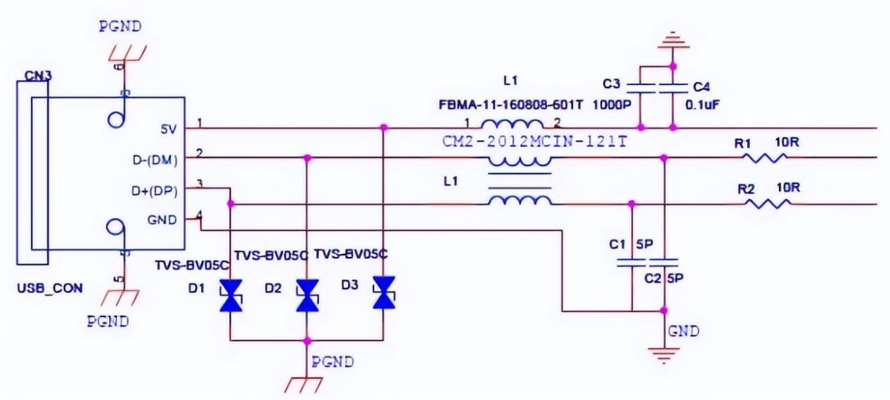
Figure4:Typical application
1.4 How to Choose a TVS Diode?
In essence, there are a number of important differentiators and deciding considerations when selecting a TVS diode. Although a TVS diode selection guide should be able to assist you in making the optimum component choice for your system, there are a few key considerations you should make.
The following crucial characteristics should always be taken into account to assist you in getting started:
- Configuration
- Clamping Voltage
- Peak pulse current
- Physical dimensions
In addition to the qualities mentioned above, further characteristics to consider include:
Breakdown Voltage is the voltage rating at which the diode starts to safeguard the circuit and channel current out of it to the ground.
The operating voltage that should not be exceeded is the reverse stand-off voltage.
The precise kind of diode you want is the last thing to think about when selecting a TVS diode. The key types are further examined in the section that follows.
Ⅱ Semiconductor Discharge Tube (TSS)
2.1 Device Characteristics
The semiconductor discharge tube is a power electronic semiconductor device with miniaturization, fast response speed, and high reliability. It has a five-layer double-terminal symmetrical structure design. The features are as follows:
- Fast response and low residual pressure;
- High reliability and good consistency;
- Long service life, can be used repeatedly for a long time;
- Have relatively low junction capacitance;
2.2 Working mode
The working mode of the semiconductor discharge tube is: when the applied voltage is lower than its off-state voltage VDRM, the leakage current of the semiconductor discharge tube is extremely small, which is equivalent to an open circuit; when the external voltage is greater than VDRM, breakdown begins to occur; when the external voltage is further increased After the voltage is high, the two ends of the semiconductor discharge tube become conductive, which is equivalent to a short circuit, which can discharge a large current; when the external voltage is removed, the tube can return to the off state.
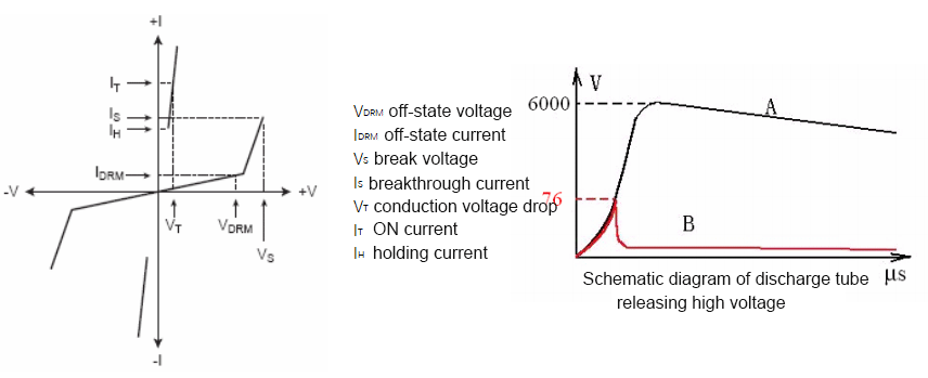
Figure5: Working mode
In the schematic diagram of the discharge of the semiconductor discharge tube above, A is the simulated lightning voltage waveform, and B is the simulated voltage waveform of the semiconductor discharge tube.
2.3 Typical applications
Semiconductor discharge tubes are mainly used in 485 circuits, video interfaces, XDSL, telephone interfaces, and other interfaces that require lightning protection.
The following is a case where a DSL telephone port uses a semiconductor discharge tube TSS for protection.
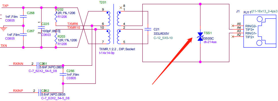
Figure6: Typical applications in circuits
Ⅲ Gas discharge tube (GDT)
3.1 Device characteristics:
A gas discharge tube, Gas discharge tube-GTD, is a device consisting of one or more discharge gaps sealed in the gas discharge tube medium, used to protect equipment or people from high voltage hazards. Commonly used in electronic products are ceramic gas discharge tubes. The main features are a large flow rate, low junction capacitance, and high insulation. Mainly to prevent electronic products from being struck by lightning.
3.2 Working process:
Normally in a high-impedance state——(after the external high voltage is connected)——enter the glowing state——enter the arc light state—(after the external high voltage disappears)——enter the glowing state——return to the high resistance state.
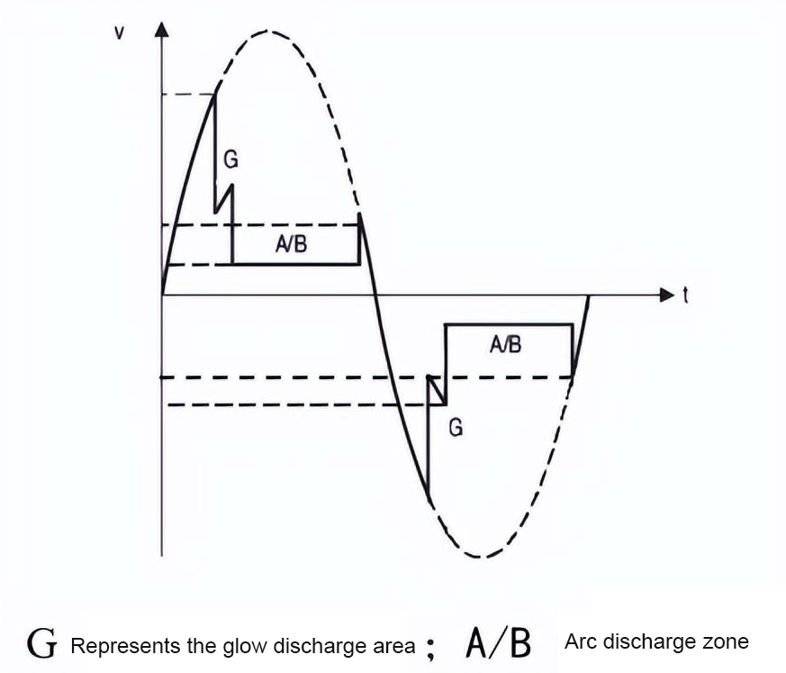
Figure7: Working process
3.3 Typical Application:
Gas discharge tubes are mainly used in AC power supply, DC power supply interfaces, 485 circuits, video interfaces, XDSL, Ethernet interfaces, and other interfaces that require lightning protection.
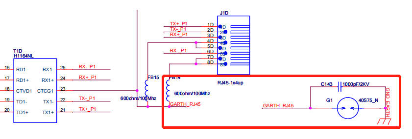
Figure8: Gas discharge tubes are mainly used in AC power supply
3.4 How to Choose Gas Discharge Tubes?
DC Spark-over Voltage and Impulse Breakdown Voltage
When choosing a type, care should be taken to consider the distinction between DC spark-over voltage and pulse breakdown voltage. The working voltage of the circuit, which must be higher than the protected circuit's maximum working voltage, should be the DC spark-over voltage. If not, it will interfere with the circuit's regular functionality. The pulse breakdown voltage and the surge's rate of voltage rise are connected. The diagram of the GDT's on-state voltage at various rising rates is shown in Figure 4. The chart shows that the breakdown voltage of GDT increases with an increasing rising rate.
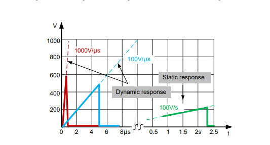
Figure 9: Diagram of GDT’s On-state Voltage at Different Rising Rates
GDTs Follow Current Problem
The GDT is a switching-over voltage protection device that cannot be used to protect high-voltage power circuits because of its low on-state voltage. It is frequently claimed that GDT has followed currents, which means that GDT will always be in on the state if the working voltage of the protected circuit is higher than the on-state voltage of GDT. GDT and the circuit will be harmed if there are strong currents flowing through it at the amperage level.
Ⅳ TVS vs TSS vs GDT
4.1 Application fields:
TVS is more used in lower voltage interfaces and directly protects key ICs in circuit boards. Such as ESD protection especially for ICs.
TSS is more used in the secondary protection of lightning strikes and transient phenomena including AC in telecommunication equipment, such as telephones, fax machines, modems, program-controlled switching and network equipment, and analog and digital lines such as xDSL.
GDT is mainly used in power ports, RS485, network ports, optical ports of communication products, industrial products, monitors/ultrasound, and other medical equipment; AC power ports and coaxial ports of consumer electronics such as set-top boxes/electronic toys; TV sets/ AC power port, RS485/HDMI for digital cameras, etc.
4.2 Voltage class division:
TVS is more used in environments below 30V, and the diodes integrated into most IC chip ports can only withstand ESD not exceeding 2KV. The important indicator of TVS devices is the electrostatic voltage that can be suppressed, such as 15KV (air electrostatic discharge voltage) and 8KV (contact electrostatic discharge voltage).
TSS is more used in environments above 50V. Typical applications include 200V for communication lines; 58V for secondary protection circuits of program-controlled switches.
GDT is generally used in 70V-3600V, mainly for lightning protection.
Ⅴ Frequently Questions Asked about EMC Components
1. What is EMC electrical?
ElectroMagnetic Compatibility (EMC) is a characteristic of electrical and electronic equipment that permits it to operate as intended in the presence of other electrical and electronic equipment, and not to adversely interfere with that other equipment.
2. What are EMC components?
- EMC Components (Common mode Noise Filters, Shield Film) Common mode Noise Filters. Electromagnetic Wave Shield Film. EMI Filters (Discontinued Products)
- Circuit Protection (ESD, Surge, Fuse, etc.) Varistors (ZNR Surge Absorber) Fuses.
3. What is the meaning of EMC?
Electromagnetic Compatibility
Electromagnetic Compatibility (EMC) and Radio Frequency (RF) Testing. Electromagnetic Compatibility, also known as EMC, is the interaction of electrical and electronic equipment with its electromagnetic environment, and with other equipment. All electronic devices have the potential to emit electromagnetic fields.
4. What does a transient suppressor do?
A transient voltage suppressor (TVS) is an avalanche diode specially designed to clamp overvoltages and dissipate high transient power surges. ST's Transil™ protection devices are able to shunt a high current surge for a short duration.
5. How does a transient voltage suppressor diode work?
Transient Voltage suppressors are typically placed in parallel with the circuit. They filter current to protect the circuit and can act to suppress the amount of Voltage that can pass through a junction at any given time. This is highly useful in the event of spikes occurring.
6. What is the function of the TVS diode?
TVS diodes absorb abnormal voltage from interfaces, external terminals, etc., prevent malfunction of circuits, and protect devices. They are suitable for absorbing and suppressing static electricity or short-pulse voltage.
 A Comprehensive Guide to Grasping FPGA Structure6/20/2024 377
FPGA (Field-Programmable Gate Array) is an integrated circuit, a type of programmable chip, that allows engineers to program custom digital logic. It can change its hardware logic based on the program, with the primary purpose of enabling engineers to redesign and reconfigure their chips faster and cheaper, whenever they want. However, nothing in the world is ideal, and FPGA chips also have limitations!
Read More > The EU to Impose Tariffs on Electric Vehicle Imports from China in Early July6/17/2024 263
The EU to Impose Tariffs on Electric Vehicle Imports from China in Early July
Read More > What is XC7A100T-2FG484I?6/6/2024 297
XC7A100T-1CSG324C is an FPGA-based digital signal processing board, which consists of Xilinx's Virtex-7 series chips and FPGA interface chips.
Read More > Analog cycle inventory hits bottom, AI drives flash memory demand to continue6/4/2024 394
Analog cycle inventory hits bottom, AI drives flash memory demand to continue
Read More > Micron Plans to Build a Factory in Japan, NAND Flash Prices May Remain High5/31/2024 467
Micron Plans to Build a Factory in Japan, NAND Flash Prices May Remain High
Read More >
Hot News
- Diode Overview: Application in Automotive Alternator Rectifiers
- Voltage-Controlled Oscillator: Principle, Type Selection, and Application
- Ultra-low power consumption of STM32U575/585 microcontrollers(MCU)
- Electronic Component Symbols: Resistor, Capacitor, Transformers and Connectors
- The Best Guide to Transistor
- Basic Information about Temperature Sensor


