The TL074 Operational Amplifier: A Comprehensive Exploration
Introduction
Few parts in the field of integrated circuits are as highly esteemed as the TL074 operational amplifier. The TL074, created by the esteemed Texas Instruments, is a perfect example of how to combine precise engineering with flexible functionality. This modest-looking quad op-amp, with four separate amplifiers housed inside, is a marvel of contemporary electrical engineering.
Table of Content
What is TL074 Operational Amplifier?
The TL074 is a JFET-input quad operational amplifier that is widely used in integrated circuits. It is a JFET-input operational amplifier family member and is renowned for its low noise, wide range of applications, and high input impedance. The TL074 is a quad op-amp, designed by Texas Instruments, which means it has four separate amplifiers in one package. This makes it an affordable and room-saving option for a range of electronic tasks.
TL074 Pinout

TL074 Operational Amplifier Pinout
TL074 Pin Configuration
|
PINS |
Pin description |
|
1 (Out 1-Output 1) |
the output pin of 1st OP-AMP |
|
2 ( Input 1-inverting Input) |
inverting input voltage to 1st OP-AMP |
|
3 ( Input 1- non-Inverting Input) |
non-inverting input voltage to 1st OP-AMP |
|
4 (Vcc+) |
connect the positive supply voltage |
|
5 ( Input 2- non-Inverting Input) |
non-inverting input voltage to 2nd OP-AMP |
|
6 ( Input 2-inverting Input) |
an inverting input voltage to 2nd OP-AMP |
|
7 (Out 2- Output 2) |
output of 2nd OP-AMP |
|
8 (Out 3- Output 3) |
output of 3rd OP-AMP |
|
9 ( Input 3-inverting Input) |
an inverting input voltage to the 3rd OP-AMP |
|
10 ( Input 3- non-Inverting Input) |
non-inverting input voltage to 3rd OP-AMP |
|
11 (Vcc-) |
connecting negative supply voltage |
|
12 ( Input 4- non-Inverting Input) |
non-inverting input voltage to 4th OP-AMP |
|
13 ( Input 4-inverting Input) |
an inverting input voltage to the 4th OP-AMP |
|
14 (Out 4- Output 4) |
output of 4th OP-AMP |
TL074 CAD Model
Symbol

Footprint

TL074 Features and Specifications
JFET Input Operational Amplifier Quad Package
Available in Different Packages like 14-pin PDIP, TSSOP, SO-14, with different variations like TL74AB, TL74A, TL74L & TL74AC
Usual Operating Voltage ranges from +15V to -15V
Protection of Output Short Circuit
Operating Voltage Max is 36V
I/P Bias Current is 65pA
Propagation delay (Pd)/max transition time is 29 ns
CMRR (Common Mode Rejection Ratio) is 100dB
Low-Level Input Voltage is 0.8V
Input (i/p) offset voltage is 10 mV
Input (i/p) bias current is 200 nA
Input (i/p) offset current is 100 nA
The current Supply is 2.5 mA
Slew Rate is 13 V/µs
Power Dissipation is 680 mW
O/p short circuit current is 60 mA
Differential i/p Voltage is ±30V
The input range (i/p) Standard Mode There is -12V to +15V voltage.
The large signal's voltage gain is 200 V/mV.
Voltage Supply's rejection ratio is 86 dB.
How to use TL074 Operational Amplifier?
Two terminals 4 & 11 supply power to TL074 operational amplifier (IC). In this case, pin4 connects to the +Ve power supply. The pin 1 power supply is for the -Ve. Pin 2 of the first op-amp receives an inverting input, while Pin 3 of the second op-amp receives a non-inverting input. Pin 1 is where the first op-amp output is obtained. Pin 6 receives an inverting input for the second operational amplifier, while Pin 5 receives a non-inverting input. Pin 7 is where this op-amp output is accessible. The third integrated circuit (IC) has an inverting input at pin9, a non-inverting input at pin10, and an output at pin8.
How to deal with unused TL074 Pins?
Not all four ICs are utilized because packages like the Quad Op-Amp are included in ICs like the TL074. In this case, the unused op amp terminals need to be properly terminated, otherwise, these pins will accumulate some capacitance, which will affect the circuit performance.
The operational amplifier used in the circuit will consume a lot of power, thus reducing the design efficiency. There are several ways to terminate an op-amp depending on the circuit design, but the most common one is that the op-amp operates between voltage ranges such as Vdd and Vss. To terminate the IC, the op-amp inverting pin is connected to the o/p pin and the non-inverting pin can be supplied from a stable voltage source. The stable voltage value can be any value, but it must be within the limits of the voltage supply.
Where to use TL074?
There are four integrated circuits (ICs) in the TL074 operational amplifier, and each amplifier can be used independently. The primary characteristic of the TL074 operational amplifier is the high-voltage JFET and BJTs used in it, which enable the transistor to have a very high i/p impedance and a low bias current. Due to its reduced noise and harmonic distortion, this integrated circuit is utilized in audio preamplifiers. If you're looking for an IC driven with JFET & Quad packaging, this one is a good fit.
TL074 Applications
- voltage follower
- Unity gain inverting amplifier
- bilateral current source
- AC/DC converter
- instrumentation amplifier
- square wave generator
- voltage comparator
- Power supplies
- oscillators
- half-wave rectifiers
TL074 Practical Examples
- on our mobile phones for AD conversion
- In Audio amplifiers
- Programmable logic controllers
- Video signal conditioning units
- Processors
- Sensor Data Accusation
- digital to analog converters in Phone
- Temperature sensors and controllers
- Error amplifiers
- communication circuits
- Mobile phone chargers
- Receivers
- Modulators
- Synthesizers
Headphone Amplifier using TL074 Op-Amp
This op-amp is an essential component to drive a headphone.

This circuit supplies the amplifier circuit with voltage using a single TL074 integrated circuit and a 9V battery.
The maximum power of this headphone amplifier, according to theory, is around 100 terms (200 mW peak) at 32 ohms load via a voltage gain of 7.6x (17.6 dB).
Harmonizing Active Filters: To provide the resonance required for signal conditioning in a variety of scenarios, the TL074 coordinates the construction of active filter circuits. Its accuracy guarantees that the intended frequencies seem pure and clear. Here is an example of TL074 as a positive feedback bandpass filter is shown as:

What is the Equivalent and Alternative of TL074?
Alternative options
2D Model (CDIP)

Conclusion
This post introduced the TL074, a high-speed JFET input quad operational amplifier. Its main features are small input bias, high slew rate, small offset current, temperature coefficient, and offset voltage. At present, the TL074 operational amplifier can be used in different packages, such as DIP (dual in-line package) and SO-14 (small outline package). Its application is also very wide, and it is a popular choice in the industry.

 DC-DC converter RFB-0505S: Specification,Datasheet,Features and Applications6/13/2024 310
The RFB-0505S is a DC-DC converter from RECOM Power, Inc., belonging to the RFB Series. It features a Single In-Line Package (SIP7) and provides a single unregulated output. This converter offers 1 watt of power with an output voltage of 5V and is rated for an isolation voltage of 1kV.
Read More > Understanding the RFMM-0505S DC-DC Converter: A Comprehensive Guide6/4/2024 460
In the world of electronics, ensuring efficient power management is crucial for the performance and reliability of devices. One of the key components in achieving this is the DC-DC converter. Today, we dive into the specifics of the RFMM-0505S DC-DC converter, exploring its features, applications, and benefits.
Read More >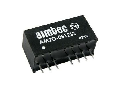 12V DC-DC Converter AM2G-0512SZ: Specifications, Datasheet, Applications and Features6/3/2024 388
A DC-DC converter is an essential electronic device to convert a direct current (DC) source from one voltage level to another. These converters are widely employed in various applications, including portable electronic devices, automotive systems, and renewable energy installations.
Read More >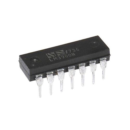 What is LM3900 Quadruple Norton Operational Amplifier?5/30/2024 664
The LM3900 consists of four independent dual-input internally compensated amplifiers. These amplifiers are specifically designed to operate on a single power supply voltage and provide a large output voltage swing. They utilize current mirrors to achieve in-phase input functionality. Applications include AC amplifiers, RC active filters, low-frequency triangle waves, square wave, and pulse waveform generation circuits, tachometers, and low-speed, high-voltage digital logic gates.
Read More >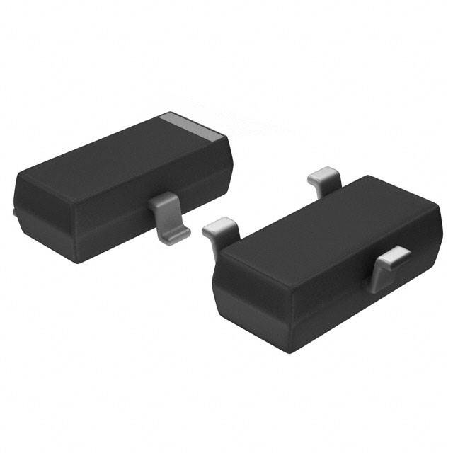 Exploring the MMBT3906 Transistor: A Comprehensive Guide5/24/2024 486
The goal of the Taiwan Semiconductor MMBT3906 PNP Bipolar Transistor is to provide a high surge current capability with minimal power loss. This transistor is perfect for automated installation and has high efficiency.
Read More >


